
Walk through a switchgear build and you will find the least glamorous parts doing the hardest work. One of them sits in the gap between a current-carrying busbar and the grounded enclosure. It has to pass heat along and hold voltage off at the same time, and keep doing both after a thousand thermal cycles.
A filled plastic spacer struggles with that combination. A solid ceramic block handles the heat but is brittle in a bolted joint. That gap is why we build Mica-Ceramic Composite Parts at NBRAM, and the duty they face is worth spelling out.
A loaded busbar joint runs hot. Copper at 200°C is routine inside a panel, and fault conditions push local temperatures far higher. A Mica-Ceramic Composite Part is rated for continuous duty from -60°C to 950°C and survives rapid cycling between those extremes without cracking or delaminating.
The electrical numbers are where it gets interesting. Dielectric strength lands between 15 and 25 kV/mm depending on thickness. Volume resistivity holds above 1014 Ω•cm even after prolonged exposure to high temperature, which is the figure that actually matters. Plenty of insulators look fine on a datasheet and then drift once they have sat at temperature for a few hundred hours.
Heat still has to move. We target 1.5-2.5 W/m•K, which spreads the load away from the joint without turning the spacer into a path for anything except heat.
The usual route to a part like this is to stir ceramic filler into a polymer. It is cheap, and it works until the polymer ages out. We build ours the other way round. Mica platelets are oriented parallel to the surface, which forms a layered barrier that resists electrical tracking across the face of the part, and the ceramic phase is co-fired with that structure rather than glued to it.
Keeping the two phases together is the whole trick. The ceramic formulation uses additives selected to match the thermal expansion coefficient of the mica, so both expand and contract at the same rate instead of tearing at the interface. That interface is where most composite insulators eventually give up.
A Mica-Ceramic Composite Part runs from 0.5mm to 25mm thick. Inside that range we can bias the formulation toward thermal performance or toward dielectric strength, because the two rarely peak at the same point and the customer usually knows which one is binding.
Every batch is CT scanned. Micro-voids and delamination are the two defects that a visual inspection will not catch and a bench dielectric test will not always catch either. They surface two years into service instead.
Finding them on the scanner is far cheaper than finding them in a warranty claim. NBRAM has been producing mica and thermal-management components in Ningbo since 2004, works to ISO9001, and ships RoHS (2011/65/EU) compliant parts to customers across Europe and Asia.
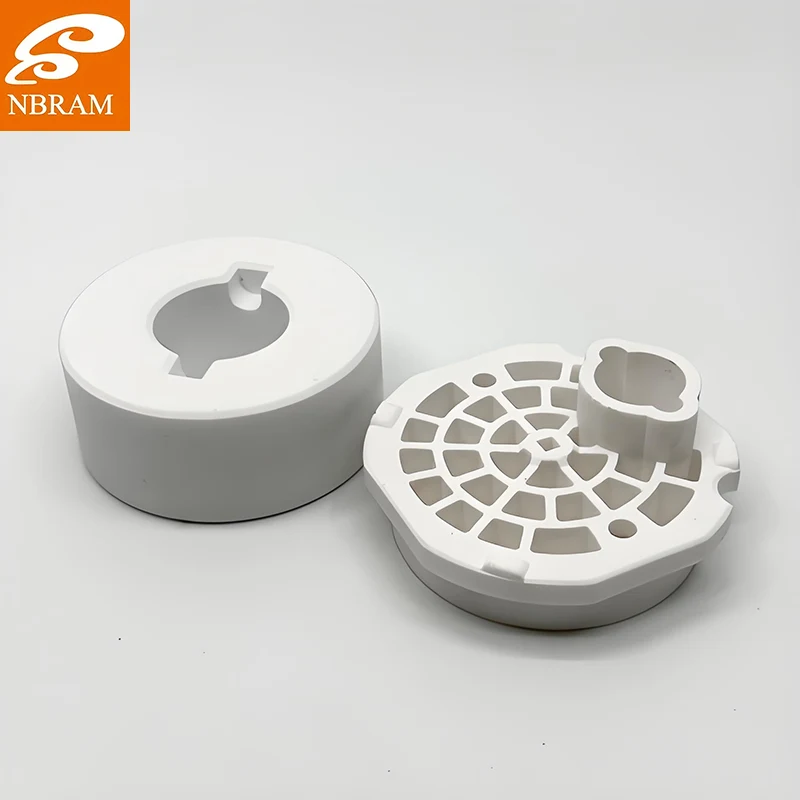
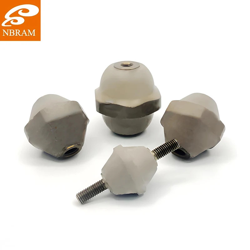
Standard plate stock is rarely the answer. Busbar and power-electronics projects usually need a specific outline: holes, slots, cut-outs for fasteners, a stepped edge to clear a connector. We machine and stamp Mica-Ceramic Composite Parts to the drawing, and where a part has to be married to metal hardware, it ships as a finished insulation assembly rather than loose plates.
Send the drawing along with the duty: continuous temperature, working voltage, and the thickness you have room for. We will tell you which formulation to run and where the realistic limits sit.
Start with the Mica-Ceramic Composite Part specification, or see how it ends up in finished hardware under Mica Insulation Assemblies and CNC Machined Mica Components. A sample for your own thermal cycling rig is usually the quickest way to settle the question, so ask for one.