
Clamp a thermal protector into a test rig, tape a thermocouple to the case, and log the reading at the instant the contacts open. On a unit marked 150°C the log will usually sit above 150. That is not a bad part. It is what the setpoint actually describes, and reading the three numbers on the label correctly decides whether the protection works in the field or nuisance-trips in the first week.
The 50°C to 150°C range of our thermal protector line is referenced to the bimetal disc inside the housing, not to the surface you can touch. The disc follows the case with a delay, and that delay is published rather than hidden: response time runs 5 to 15 seconds, and it shifts with the temperature difference the part sees.
Which explains the rig result. A slow oven ramp gives the case time to catch up, so the trip lands near nominal. A stalled motor winding heats in seconds, the case lags, and an external probe reads high at the moment of break. If your acceptance test uses a fast ramp, the number you record is a system number, not the disc number.
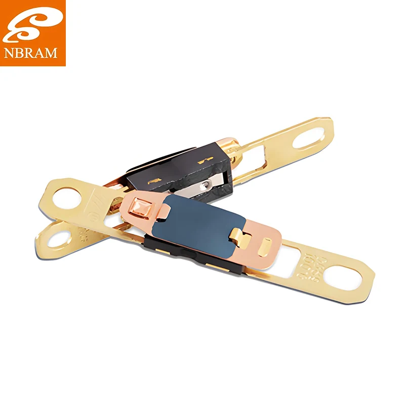
Standard accuracy across the range is ±3°C, and we also build ±2°C models for applications with a tighter window. Take that literally. A 150°C part is in specification anywhere from 147°C to 153°C at the disc, and two units out of the same batch can sit at opposite ends of that band and both be correct. If the gap between normal running temperature and the insulation limit of your motor is only 6°C, the band has to be part of the selection work, not a footnote.
Reset behaviour is the other half of the choice. Automatic reset typically returns within 2 to 3 minutes of cooling, and that window can be customized. A fast reset turns a persistent fault into repeated cycling, which is hard on contacts. A slower one holds the machine off long enough for heat to leave the windings. Neither is right until you know the load and how the operator will respond to a trip.
Current ratings span 1A to 25A at 250V AC. What decides whether a 25A part survives a hard fault is contact resistance, held below 30mΩ in our units. Run 20A through 30mΩ and the contacts dissipate 12W inside a component smaller than a thumb. That heat sits millimetres from the bimetal that is trying to sense something else, so the contact set is not a commodity item. Ours use silver-cadmium oxide, chosen for arc quenching when the circuit breaks under load.
The isolation side is simpler to state: insulation resistance above 100MΩ at 500V DC, dielectric strength of 1500V AC held for one minute without breakdown. Those two figures cover leakage and isolation for a 250V circuit. Below them, every unit is load tested at its rated current rather than buzzed with a multimeter, because a contact that reads fine at 100mA can weld shut at 20A.
Each protector is calibrated at several temperature setpoints rather than one. The technician adjusts the bimetal while watching both trip temperature and reset behaviour, since a part that trips on the nose but hesitates to reset will fail in service just as surely as one that trips early. Thermal cycling, dielectric verification and response time measurement follow. Samples from each batch are pushed past their rating to leave a margin that normal production testing will never show.
Housing and sealing follow the environment. Glass-filled nylon covers most appliance and motor work. Industrial cabinets and wet locations get stainless steel housings with laser-welded seals instead of epoxy potting, which matters where oil mist or washdown is routine.
If you are narrowing a part number for a motor, a transformer or a power supply, send the trip window, the fault current and the reset expectation. We will match a standard unit or build to the tolerance you need, and a sample can be on its way before the drawing is final. Start from the Thermal Protector page, or compare it against a bimetal thermostat and a one-shot thermal fuse if your circuit needs a different protection strategy. More temperature control options sit under Other Temperature Controller.