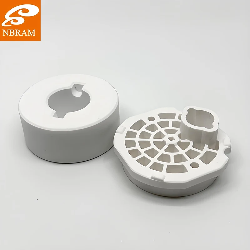

Ask anyone who has cut a refinery turnaround short and you will usually hear the same two reasons: the joint started weeping at the edge, or a stray current found a path through the bolts. The iron mica insulation gasket sitting between those flanges is the cheapest item in the assembly and the one that decides both questions.
We hot-press laminate iron plate to muscovite mica at NBRAM to make these parts. Datasheets for insulation gaskets tend to mix hard limits with soft language, so here is the walk-through we give customers when they ask which figures actually constrain a design and which ones are just there to fill the page.
Thickness covers 0.5mm to 6.0mm and every sheet is held to ±0.02mm. That tolerance matters more than the thickness value itself. On a stack of several gaskets the errors add up, and if each part can drift a tenth of a millimetre the bolt load never spreads evenly across the flange face.
On the common 2.0mm grade we control surface flatness below 0.02mm/m², so the gasket meets the flange over its whole area instead of bridging high spots. Standard outlines run from 10mm to 1000mm, and we punch or drill custom hole patterns when the drawing calls for a port or a bolt circle that does not match the catalogue.

Dielectric strength holds at 18-25 kV/mm at 600°C, and volume resistivity stays above 5×10¹² Ω·cm even while the gasket sits under continuous compression. Those two figures are what separate an insulation gasket from a plain iron spacer, and they are the ones buyers ask us to certify batch by batch.
Compressive strength lands between 150 and 300 MPa depending on thickness. That is the range that keeps the mica from squeezing out of the joint when bolts are torqued to a pressure vessel spec. Dimensional stability stays inside 0.01% while the part cycles between room temperature and 800°C, and the coefficient of thermal expansion is 10-15×10⁻⁶/°C, within a few points of carbon steel, so gasket and flange move together instead of fighting each other.
Thermal conductivity is 8-15 W/m•K, which is high for an insulator and entirely deliberate. The iron facing carries heat away from the sealing line, so the mica is not the only barrier standing between process temperature and the flange bolts. A design that needs a true thermal break is asking this material to do a job it was not built for.
We start with iron plate and premium muscovite mica, then laminate under hot-press equipment that holds bonding pressure within ±0.5% across the run. Layer adhesion comes out at 25-35 MPa, verified by ultrasonic monitoring while the press is still closed rather than after the fact, because a void between layers will not show on a finished part.
Edge sealing gets its own operation. An electrochemical treatment closes the cut edge without breaking the insulation path, which is the step that stops fluid wicking in along the mica on a wet or corroded line. Finished gaskets are salt-spray tested past the ASTM B117 threshold, with documented protection beyond 1000 hours, and pressure-cycled samples are measured for dimensional drift.
Most failures we are asked to diagnose come from a part bought on thickness alone. Pressure vessel work normally cites ASME B16.20 or API 6A, and the certification package has to travel with the gasket for the inspector. Give us the flange standard, the bolt load, the maximum service temperature and the fluid, and the thickness and edge treatment follow from those inputs instead of being guessed first.
NBRAM has been making mica and thermal insulation parts in Ningbo since 2004, with ISO 9001 quality control and RoHS-compliant materials across the range. Trial samples of the iron mica insulation gasket are available for test assemblies, and we quote punched or drilled parts against your drawing through the Stamped Mica Parts range. Where a joint needs a machined shoulder or a bonded stack instead, the same material is built into our Mica Insulation Assemblies line.